Errors In The Datasheet Or Exercises In Trigonometry
I came across an interesting approach to solving the problem of doubling the frequency in circuitry: use an analog multiplier. Indeed, if the incoming signal is a sine wave, then what could be simpler than multiplying the incoming signal by itself, i.e. squaring of the sine wave, so that at the output we will get a double frequency signal:
\[\sin(x) \cdot \sin(x) = \frac{1}{2} [1 - \cos(2x)]\]However, looking into the details of the proposed solution in the datasheet for the AD633 device, one can stumble upon unpleasant mistakes in calculations:
But first things first.
What kind of beast is the analog multiplier?
Exactly what name describes: the device multiplies two signals, the voltages on the input, and outputs the voltage as a result of multiplication.
The following is the functional block diagram from the datasheet of the AD633 analog multiplier, which I chose because of the reasonably low price:
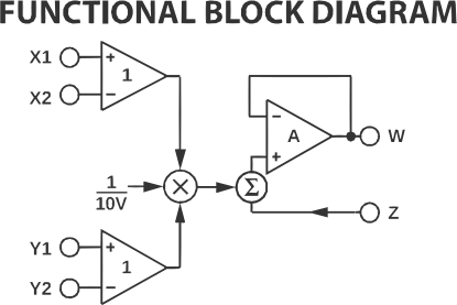
This device does more than only multiplication and the output function can be represented by the following equation:
\[W = \frac{(X1 - X2) \cdot (Y1 - Y2)}{10V} + Z\]Which in simple words means: multiply the difference between inputs, attenuate by a factor of 10 and add another signal. Attenuation and additional input Z we won’t take into account in further calculations thus ignore them.
The analog multiplier is used in many application such as modulation, demodulation, phase detection, amplifiers, attenuators, voltage-controlled filters. One of such applications is frequency doubling of the input signal by squaring, the use case I’m reviewing in this article.
Squaring and frequency doubling
The common use case of the frequency doubling is carrier recovery in signal demodulation, such as for example BPSK demodulator circuits. There are various approaches and various schematics that double the frequency of the input signal, but I find that the solution using an analog multiplier is very simple (requires minimum components) and borders on mathematics and electrical engineering, so it is very tempting to use it.
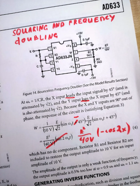
The datasheet proposes the following wiring to achieve frequency doubling:
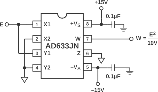
“Squaring of an input signal, E, is achieved simply by connecting the X1 and Y1 inputs in parallel to produce an output of E²/10V” proposes the datasheet. Indeed, having the X2, Y2 and Z connected to the 0V (ground) we have the following equation:
\[W = \frac{(E - 0) \cdot (E - 0)}{10V} = \frac{E^2}{10V}\]So when the input is a sine wave, then according to the product of sines:
\[\sin(x) \cdot \sin(y) = \frac{1}{2} [\cos(x - y) - \cos(x + y)]\]we have:
\[\sin(x)^2 = \frac{1}{2} [\cos(0) - \cos(2x)] = \frac{1}{2}[1 - \cos(2x)]\]Below is a SPICE simulation of an AD633 analog multiplier that squares a 10 kHz sine wave and whose output is:
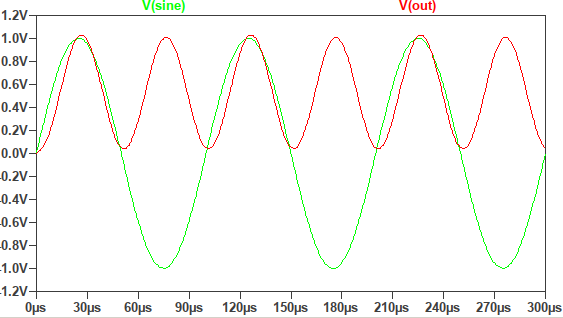
NOTE: The “out” signal is not attenuated by a factor of 10 as supposed to be according to the datasheet. For the sake of simplicity and clarity of signal presentation I avoid attenuation.
Unfortunately, squaring the sine wave introduces a troublesome characteristic: the presence of a DC term that raises the signal above zero, such that the signal always has a positive value. One obvious solution is to incorporate a high-pass RC filter to block this DC component. However, the authors of the datasheet propose something more mathematical, namely instead of squaring the \(\sin(x)\), multiply \(\sin(x)\) and \(\cos(x)\), which gives us different equation without the DC component:
\[\sin(x) \cdot \cos(x) = \frac{1}{2} [\sin(0) + \sin(2x)] = \frac{1}{2}\sin(2x)\]This is indeed Mathematical! The only thing left is to turn the input sine into a cosine and here is exactly where the resulting calculations in the datasheet are incorrect. Let’s go deeply.
Proposed idea in the datasheet
To eliminate the DC component resulting from squaring the sine wave, the input signal can be split into two and individually transformed. One signal delays the input by 45°, while the other leads the input by 45°. This results in \(\sin(x — 45^{\circ})\) and \(\sin(x + 45^{\circ})\), with both signals being 90° out of phase. This satisfies the identity of sine and cosine multiplication and effectively doubles the frequency. To achieve this signal transformation, a series RC circuit can be used. However, it’s important to note that an RC circuit alone cannot achieve a complete 90° phase shift. Therefore, we apply a phase shift of -45° to the Y input and a phase shift of +45° to the X input by subtracting the sines.
The proposed wiring from the datasheet looks like the following:
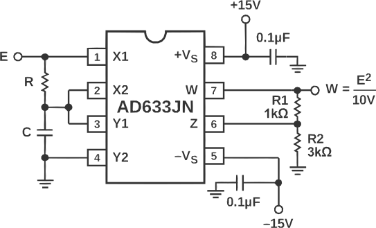
Where the connection of inputs X and Y through the RC circuit gives us the following equation:
\[\begin{align} W &= \frac{(X1 - X2) \cdot (Y1 - Y2)}{10V} \\ \\ &= \frac{[\sin(x) - \frac{1}{\sqrt{2}}\sin(x - 45^{\circ})] [\frac{1}{\sqrt{2}}\sin(x - 45^{\circ}) - 0] }{10V} \tag{1}. \end{align}\]Using identity
\[\sin(x \pm y) = \sin(x)\cos(y) \pm \cos(x)\sin(y)\]we can simplify the \(\frac{1}{\sqrt{2}}\sin(x - 45^{\circ})\) in the first square brackets as the following:
\[\frac{1}{\sqrt{2}}\sin(x - 45^{\circ}) = \frac{1}{2}\sin(x) - \frac{1}{2}\cos(x),\]so the equation \((1)\) becomes
\[\begin{align} W &= \frac{[\sin(x) - \frac{1}{2}\sin(x) + \frac{1}{2}\cos(x)] [\frac{1}{\sqrt{2}}\sin(x - 45^{\circ})]}{10V} \\ \\ &= \frac{[\frac{1}{2}\sin(x) + \frac{1}{2}\cos(x)] [\frac{1}{\sqrt{2}}\sin(x - 45^{\circ})]}{10V} \\ \\ &= \frac{[\frac{1}{2}(\sin(x) + \cos(x))] [\frac{1}{\sqrt{2}}\sin(x - 45^{\circ})]}{10V}. \tag{2} \\ \end{align}\]Replacing \(\cos(x)\) on \(\sin(90^{\circ} - x)\) and using identity
\[\sin(x) \pm \sin(y) = 2\sin(\frac{x \pm y}{2})\cos(\frac{x \mp y}{2})\]we can represent \(\sin(x) + \cos(x)\) from \((2)\) as
\[\begin{align} \sin(x) + \cos(x) &= \sin(x) + \sin(90^{\circ} - x) \\ \\ &= 2\sin(45^{\circ}) \cos(x - 45^{\circ}) \\ \\ &= \sqrt{2}\cos(x - 45^{\circ}) \\ \\ &= \sqrt{2}\sin(x + 45^{\circ}), \end{align}\]so the equation \((2)\) becomes
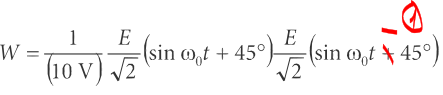
\[\begin{align} W &= \frac{\frac{1}{2} \sqrt{2}\sin(x + 45^{\circ}) \frac{1}{\sqrt{2}}\sin(x - 45^{\circ})}{10V} \\ \\ &= \frac{1}{10V}\frac{1}{\sqrt(2)} \sin(x + 45^{\circ}) \frac{1}{\sqrt{2}}\sin(x - 45^{\circ}) \tag{3} \end{align}\]And here is the first obvious typo in the datasheet, where both sines are indicated with a positive phase shift:
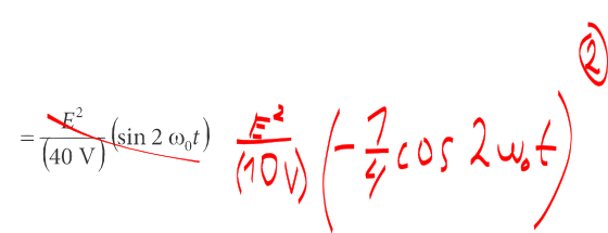
The second error is the actual result of multiplication of two sines, which gives \(-\cos(2x)\) and not the indicated \(\sin(2x)\):
The multiplication from the equation \((3)\) can be shown to be correct:
\[\begin{align} W &= \frac{1}{10V}\frac{1}{\sqrt(2)} \sin(x + 45^{\circ}) \frac{1}{\sqrt{2}}\sin(x - 45^{\circ}) \\ \\ &= \frac{1}{10V}\frac{1}{2} \sin(x + 45^{\circ})\sin(x - 45^{\circ}) \tag{4} \end{align}\]Again using identity
\[\sin(x \pm y) = \sin(x)\cos(y) \pm \cos(x)\sin(y)\]the equation \((4)\) can be represented as
\[W = \frac{1}{10V}\frac{1}{4}(\sin^2(x) - \cos^2(x)). \tag{5}\]From identity \(\sin^2(x) + \cos^2(x) = 1\)
\[\begin{align} W &= \frac{1}{10V}\frac{1}{4}(1 - \cos^2(x) - \cos^2(x)) \\ \\ &= \frac{1}{10V}\frac{1}{4}(1 - 2\cos^2(x)) \tag{6} \end{align}\]Using identity \(\cos(x)\cos(y) = \frac{1}{2}[\cos(x - y) + \cos(x + y)]\) the final equation looks as the following:
\[W = \frac{1}{10V}[-\frac{1}{4}\cos(2x)]. \tag{8}\]Continuing the analysis, if the input is \(\sin(x)\) and the output is \(-\cos(2x)\) (amplitude coefficient is ignored), then each positive peak of the incoming sine must be aligned with the positive peak of the outgoing cosine of twice the frequency, because:
\[\sin(\frac{\pi}{2}) = -\cos(\pi) = 1\]and this alignment of positive peaks is clearly visible on the SPICE simulation, which shows that the obtained result is correct:
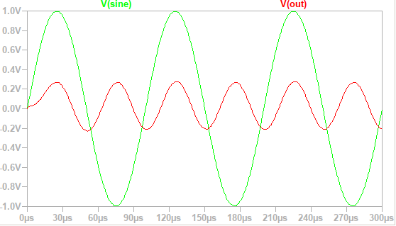
The output signal is attenuated by a factor of 4 and does not have a DC term (oscillates around 0), which also corresponds to the previous calculation.
If we compare the incorrect result \(\sin(2x)\), indicated in the datasheet, with the correct \(-\cos(2x)\), then the difference is only in the phase angle:
\[-\cos(2x) = \sin(2x - 90^{\circ})\]which actually can be a critical error for some applications where phase shift is required when comparing incoming and outgoing signals.
Where the true beauty resides
In the previous trigonometry exercise we obtained the correct equation of the output signal. But really interesting things were left for later. First let me remind: we transformed the incoming sine into two sines with a difference of 90° between them: one sine was shifted by -45°, and the other by +45°. And this transformation was achieved by two operations: the first is purely physical: an RC circuit was used; and the second operation is purely mathematical: we subtracted the sine shifted by -45° from the incoming sine. And the true beauty is this (at least it fascinates me incredibly): it so happened that the sine can be decomposed into the sum of two sines shifted in phase by 45°each (was shown previously in \((1)\), \((2)\), \((3)\)):
\[\sin(x) - \frac{1}{\sqrt{2}}\sin(x - 45^{\circ}) = \frac{1}{\sqrt{2}}\sin(x + 45^{\circ})\]and so it happened by chance that in our physical world a sine passing through an RC circuit with certain values of resistance and capacitance, attenuates and shifts in phase, corresponding to the same function:
\[\sin(x) \xrightarrow[]{RC\ transform} \frac{1}{\sqrt{2}}\sin(x - 45^{\circ})\]We can start from the other end, from physics: since we need to get a phase shift of -45°, then according to the voltage formula across the capacitor in the series RC circuit (in full details about the theory and equations of the RC circuit, you can read, for example, here):
\[V_{c} = \frac{\sin(x - \phi)}{\sqrt{1 + (\omega R C)^2}}\]where \(\phi\) is 45° and given by \(\tan(\phi) = \omega RC\), so \(1 = \omega RC\), we get
\[\begin{align} V_{c} &= \frac{\sin(x - \phi)}{\sqrt{1 + (1)^2}} \\ \\ &= \frac{1}{\sqrt{2}} \sin(x - 45^{\circ}) \end{align}\]so we can subtract the result from \(\sin(x)\) and get the same attenuated sine signal, but out of phase by +45°, exactly what we need for our frequency doubling without a DC term. This magic of turning physics into mathematics and vice versa truly delights me.